Inline Instrumentation by Sergio Canabal |
| Let’s face it – the days of the klunky floss and marble filters sitting in the corner of your aquarium are coming to a close. Matter of fact, it seems that we are trying to remove ALL of the instrumentation from our tanks. First we moved the filter from the corner of the aquarium and hung it on the back. Then we took it out all-together and put it in the stand, with nothing but hoses leading to an inflow and outflow. Next, we figured out how to take the heater out of the tank. Then a company came along and made what was left of the visible filtration nearly INvisible, by making it out of glass!The thing is, as the planted aquarium hobby has advanced in leaps and bounds, we have begun to use some more advanced techniques for monitoring specific parameters such as pH (and in turn, CO2). Our new inline heaters also needed something IN the water to measure the tank temperature so they would “know” when to switch on and off. Some systems incorporate a fair amount of automation, such as auto top-off, auto fert/supplement dosers and even automatic water changers! Unfortunately, some of these systems have put some instrumentation back INTO our tanks – after we’ve worked so hard to get it out!
Not to fear. There has been much discussion regarding this instrumentation between hobbyists, within aquarium related hobby clubs, and through some of the online forums. Now after reading, pondering and discussing the topic, I’ve attempted to take what I believe to be the “best of the best,” and incorporate it into one somewhat simple, modular and updatable solution to take a couple of the remaining (or newly introduced) pieces of instrumentation out of your tank! Exciting isn’t it? So, here goes: Concept In this case, the unit consists of 3 “modules.” One of them accepts the pH probe, one of them the input for an Automatic Fertilizer Doser as well as feed-water from an Automatic Water-Changer. The last module accepts the temp-probe for the inline heater (in this case, one that resided in the Eheim 2128). There is a reason for this particular sequence, but we’ll get to that.
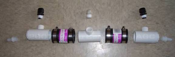
The components As you can see from the picture above, the unit consists of many parts. I’ll take you through them, from left to right. The first component is probably familiar to most. It is a basic hose barb adapter. Because this particular unit will be plumbed into the outflow of an Eheim 2217, it is a ½” barb to ½” MPT (Male Pipe Thread).
The MPT portion of the hose-barb adaptor will (after receiving Teflon tape) be screwed into the next component, below. It is actually 3 components, all of PVC, cemented together. It consists of a ½” FPT (Female Pipe Thread – accepts the MPT of the hose-barb adapter) x ¾” Slip adapter. This is cemented into a ¾” Slip x 1 & ¼” Slip adapter, which finally is cemented into one of the “hearts” of the system, the 1 & ¼” Slip x ½” FPT Reducing T. The top port of this T will ultimately accept the instrumentation. Details can be seen in the picture:
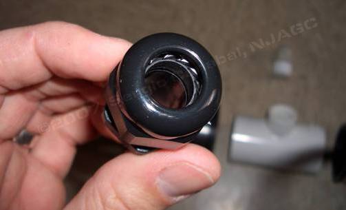
This is attached to another reducing T via a rubber hose clamp. This T is identical to the first except that it has nothing cemented to it as it does not require any hose connections. The right hand side is identical to the left, but is a mirror image of it. Now this is where it gets interesting!!! These are some cool adapters. They are ½”MPT x Liquid Tight Cord Grips made by Heyco. They basically consist of a rubber seal that can compress around a cord by tightening it. They come in different sizes, and you can order the size to match the instrument you need to fit in it! The first and third T will receive the pH probe and the temp probe, respectively.
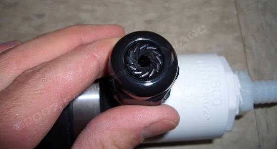
This is what this particular one looks like when it’s tightened all the way:
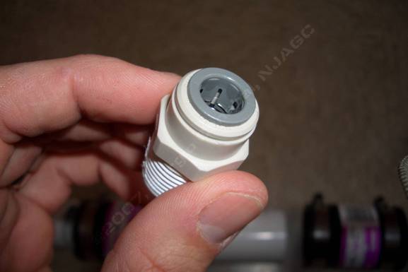
The center T will accept a ½” MPT x 3/8” JG (John Guest) RO (reverse osmosis) socket. This is where the micros, macros, Equilibrium “slurry”, and feed water will be introduced:
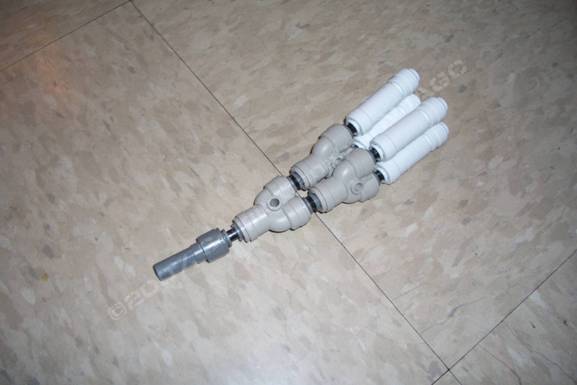
This is the contraption that will get all of those things into that one hole:
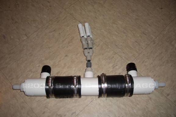
It is (left to right) a 3/8” JG Stem x ¼” JG then a ¼” JG “splitter then 2x ¼” JG splitter, then 4x ¼” JG Check Valve – don’t want micro/macros/Ca & Mg/feed water mixing up! The entire contraption looks like this:
Logic & Conclusion Now remember, water flows from the filter output left to right over the pH probe, then the “entry port,” then the temp probe. The logic for this order is that I don’t want feed water coming so directly in contact with the pH probe. I don’t have it controlling my CO2, but if I did, this might be a problem, so it’s first. Next through the “entry port.” Cold feed water coming in via the Automatic Water Changer will contact the temp probe almost immediately, ensuring the inline heater (Eheim 2128) kicks on, preventing a noticeable drop in temperature for the fish. I chose the 1 & ¼” T’s because they’re big enough to prevent reduction in flow from the probes decreasing the “passable” area for the water. As mentioned, the entire unit is modular, and can be adapted to your own set of instruments. This particular unit is roughly 16” long. It would be very easy to add, or remove a T to accommodate and additional/remove a piece of instrumentation. Of course this is just one way to do it, but I think it’s a good one. Maybe there is a better way to set this up and this will have precipitated an idea or two! |